


The performance changes in S690QL1 during bending are governed by complex metallurgical laws that differ significantly from mild steels. Understanding these laws is essential to prevent catastrophic failure in service.
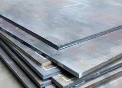
Here is a detailed analysis of the performance change laws and their engineering implications.
1. Core Metallurgical Principles: The Starting Point
S690QL1 is a Quenched & Tempered (Q&T) steel with a tempered martensitic/bainitic microstructure. This microstructure is:
Very strong (yield ≥ 690 MPa) and tough (-60°C impact).
Metastable and dislocation-rich.
Highly anisotropic (properties differ with direction relative to rolling).
Bending introduces plastic strain, which disrupts this carefully engineered state.
2. The Laws of Performance Change During Bending
Law 1: Work Hardening and Ductility Exhaustion
Mechanism: Plastic deformation introduces new dislocations and tangles existing ones, increasing strength and hardness locally but consuming the material's limited ductility.
Quantitative Change:
Surface Hardness in the strained outer fiber can increase by 50-100 HV (e.g., from ~280 HV to ~350+ HV).
Uniform elongation (the capacity for further plastic strain) in the bent region is severely reduced, potentially to near zero.
Engineering Consequence: The bent area becomes hard and brittle. It cannot accommodate further plastic deformation, making it a potential site for crack initiation under overload or impact.
Law 2: Severe Degradation of Fracture Toughness
Mechanism: Work hardening raises the Ductile-to-Brittle Transition Temperature (DBTT). The microstructure in the cold-worked zone shifts from tough tempered martensite to a strained, brittle state.
Quantitative Change: Charpy V-notch impact energy can be reduced by 50-80% at the operational temperature. A material certified for 40 J at -60°C may exhibit less than 10 J in the cold-bent region.
Engineering Consequence: The component loses its fracture safety. In low-temperature or dynamic loading conditions, a bent section can fail in a brittle, catastrophic manner with minimal warning.
Law 3: Induction of High-Magnitude Residual Stresses
Mechanism: Bending creates an imbalance: the outer fibers are in residual compression, the inner fibers in residual tension. For S690QL1, the magnitude of these stresses can approach the yield strength.
Engineering Consequence: These residual stresses algebraically add to applied service stresses.
In the tensile zone, this can push the total stress beyond yield, promoting fatigue cracking or stress corrosion cracking (SCC).
This makes the component's stress state highly unpredictable using standard design formulas.
Law 4: Anisotropy-Driven Performance Variation
Mechanism: Steel plate has directionality from rolling. Inclusions are elongated, and grains are textured.
Quantitative Change: Bending transverse to the rolling direction is more detrimental than bending parallel to it. Transverse bend toughness and ductility are inherently lower to begin with and degrade more severely.
Engineering Consequence: Bending orientation must be specified on drawings. A bend that is acceptable longitudinally may crack if performed transversely.
Law 5: The Risk of Microcracking and Delayed Failure
Mechanism: At sharp bend radii (low R/t ratios), the outer fiber strain exceeds the material's local ductility limit, causing microscopic tears at the surface.
Engineering Consequence: These microcracks are not always visible (NDT may be required). They act as potent stress concentrators and can lead to delayed fatigue or brittle fracture under cyclic or impact loads in service.
3. Governing Process Parameters & Their Effects
The severity of these changes is controlled by:
The single most important factor. Smaller R/t = higher strain = worse degradation.
Absolute Minimum: R/t ≥ 5.
Recommended for Critical Applications: R/t ≥ 7-10.
Must be validated by FEA or prototype testing. Bending Orientation Transverse bending >> Longitudinal bending in severity of toughness loss. Specify longitudinal bending wherever possible. If transverse, increase R/t ratio significantly. Bending Temperature Cold bending (< 200°C) causes maximum work hardening. Warm bending (150-300°C) can mitigate. Warm bending is strongly recommended. Temperature must stay below 400°C to avoid tempering and strength loss. Rate of Deformation Very high strain rates can adiabatically heat the bend line, but also promote brittle behavior. Use controlled, steady press brake speeds. Avoid hammering.
4. Mitigation and Control Strategies
Given these laws, bending S690QL1 cannot be a standard workshop operation. It requires a controlled process:
Design Stage:
Minimize or Eliminate Bending: Use welded or bolted assemblies instead.
Specify Generous Bend Radii: Enforce R/t ≥ 7 as a project specification.
Specify Bending Direction: "All bends to be made parallel to the rolling direction unless otherwise approved."
Fabrication Stage:
Mandatory Warm Bending: Preheat the bend line to 150-250°C. Use temperature-indicating sticks or thermocouples for control. This reduces flow stress and lowers the DBTT shift.
Tooling & Machinery: Use polished, hardened tooling to prevent surface galling and scratching, which are additional stress concentrators.
Process Qualification: For critical components, qualify the bending procedure (temp, R/t, speed) using witness coupons. Afterwards, cut up the coupons for:
Hardness Traverse across the bend.
Charpy Impact Tests on samples extracted from the bent region.
Macro-etch Inspection for microcracks.
Post-Bending Treatment (For Critical Components):
Stress Relief Annealing: Heat to 550-600°C (below the original tempering temperature), hold, and furnace cool. This reduces residual stresses and restores some toughness. Caution: This causes a slight, predictable reduction in yield strength (~5-10%).
Localized Peening: Shot peening the tensile (inner) side of the bend induces beneficial compressive stresses, improving fatigue resistance.
Inspection & QA/QC:
100% Visual Inspection (VT) under good lighting.
Mandatory NDT: Magnetic Particle Testing (MT) of the entire outer bend surface to detect microcracks.
Hardness Check: Spot-check Vickers hardness on the outer surface to verify work-hardening levels are within expected range.
5. Summary: The Bending Protocol for S690QL1
EVALUATE: Can the design avoid bending? If not, specify large R/t and longitudinal orientation.
PREHEAT: Warm bend at 150-250°C with precise control.
QUALIFY: Qualify the procedure with destructive testing on coupons.
INSPECT: Perform 100% VT and MT after bending.
MITIGATE (if critical): Apply post-bend stress relief or peening.
DOCUMENT: Record all parameters (heat number, R/t, temperature, inspection results) for traceability.
Conclusion
The performance of S690QL1 does not merely "change" during bending; it undergoes a targeted degradation of its most valued properties-toughness and damage tolerance. The laws governing this are predictable but severe.
Therefore, bending S690QL1 should be treated as a specialist, high-risk manufacturing operation, not a routine fabrication step. The additional costs of warm bending, procedure qualification, and post-bend treatments are non-negotiable investments in maintaining structural integrity. Failure to follow these controls transforms a bent component from a structural member into a pre-installed crack initiator, fundamentally compromising the safety rationale for using this high-performance steel. For many applications, it is safer and more economical to fabricate the desired shape from welded plate than to bend it.